Your cart is currently empty!
Author: James
Parallel Operation with Different Power Supply Models
Parallel Operation with Different Power Supply Models
The same model of Kikusui DC power supplies can be connected in parallel. By connecting the signal cables, one unit is set as the master unit and it can control the other units. This operation is called as ‘master-slave parallel operation’.
Master-slave parallel operation is not available when connecting the different power supply models. To increase the output capacity with the different models, the parallel operation described below is recommended. To perform this operation, you need to set the voltage or current for each unit. The simultaneous power on/off is available with the external control. Below is the operation example.
1. Parallel Operation in Constant Voltage (CV)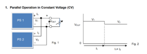
Firstly, connect two different power supplies ‘PS1’ and ‘PS2’ in parallel as shown in Fig. 1.
1. Set the output voltage for PS1 and PS2. The output voltage value for PS1 should be approx.
0.3V higher than that of PS2.
2. Set the rated CC value for PS1 and PS2.
3. Turn the output on for both units. The voltage is outputted from PS1.
4. Gradually decrease the load resistance to increase the current. Since the setting voltage for PS1 is higher, the current flows from PS1 only. When the current exceeds the rated CC value for PS1, the output voltage changes to the setting voltage for PS2. Then, the current also flows from PS2. In this example, the total current (I1+I2) is: rated CC value for PS1 + PS2 (see Fig. 2).
During this operation, the output voltage changes with the current; e.g.) It changes 0.3V in the above example. If the same voltage is set for PS1 and PS2 (the voltage difference is 0V), the current becomes unstable that alternately flows from PS1 or PS2. The required voltage difference depends on the power supply type in use. Please set the appropriate voltage difference to keep the parallel operation stable.
2. Parallel Operation in Constant Current (CC)
To operate in CC mode, it is not necessary to set a specific voltage difference on each power supply. The constant current can flow from both PS1 and PS2.Products Mentioned in this Application note:
Kikusui DC Power Supplies please see HERE
CC-CV Charging System without Series Diode
CC-CV Charging System without Series Diode
To charge batteries, it is recommended that you connect a diode in series at an output of DC power supply (See Figure 1). With a diode, constant current (CC) can be properly supplied; however constant voltage (CV) may be unstable if using remote sensing at battery terminals. Without a diode, a high current can flow between a battery and power supply when connecting or disconnecting a battery. Now, let me tell you other stable CC-CV charging methods with a switch instead of a diode.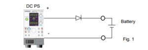
1. Connect Sense Leads to Battery
1.1 System Structure
Connect a double switch (SW1) as shown in Figure 2; one is for the output on/off switch and the other is for the sensing (+S) on/off switch.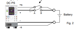
1.2 How to Set Voltage and Turn SW1 On
Set the output voltage equal to the battery voltage and then turn SW1 on.
Figure 3 shows the output voltage, output current and voltage at both terminals (A/B) of SW1 when SW1 is turned on.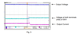
First, the output voltage increases by approx. 0.6 V because the sensing switch (+S) is open. At the time when SW1 is turned on, the small overcurrent is generated because an output current starts flowing or a switch chattering occurs. After SW1 is turned on, the output voltage becomes nearly equal to the battery voltage; the current will stop flowing.
Finally, apply CV voltage to start CC-CV charging.
Note: If you initially set CV voltage and then turn SW1 on, an excess overcurrent flows as shown in Figure 4.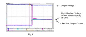
2. Connect Sense Leads to Switch
Figure 5 shows how to connect sense leads to switch (SW2). Set the output voltage equal to the battery voltage and turn SW2 on; an overcurrent will not flow.
Then, apply CV voltage to start CC-CV charging.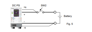
3. Others
Above systems can serve as your reference. Before configuring your own system, please be sure what type of switch you need.How do I pick the right spectrum analyser for my application?
Introduction
The SIGLENT SSA3000X, SSA3000X Plus and SVA1000X products are based on a similar swept superheterodyne spectrum analyser platform and have very similar starting prices. There are quite a few similarities, but also a few differences that could affect the end results for particular applications.
The table below compares the major specifications and the comparable options as they pertain to specific applications like VSWR.
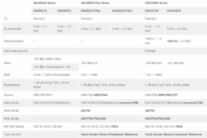
*Compatible with many commercially available return loss bridges/directional couplers
Additional SVA Features and Options
Still having trouble choosing?
Here are some additional features and options that are exclusive to the SSA PLUS and SVA platforms that may help:
Free Features:
- Touch screen control with shortcut widget
- Mouse/Keyboard support
- Easy web browser web control
- Power-On-Line – Instrument will automatically restart when power is restored to the mains power connection (power cord) when this feature is enabled.
Additional Options:
- AM/FM modulation analysis (SVA1000X-AMA. SSA3000XP-AMA) enables visualization of data encoded using AM/FM
- Digital modulation analysis (SVA1000X-DMA. SSA3000XP-DMA) enables visualization of data encoded using FSK/ASK
- Advanced measurement kit (SVA1000X-AMK, SSA3000XP-AMK) feature Harmonic and CNR measurements in addition to CHP/ACPR/TOI/OBW/Monitor.
- Mechanical calibration kit for VNA (F503ME)
If you have additional questions, you can always contact our applications team (info@siglent.com) and we would be happy to answer any additional questions you may have.
Products Mentioned In This Article:
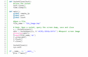
Programming Example: SSA/SVA analyser screen image capture using Python over LAN
Here is a brief code example written in Python 3.4 that uses a socket to pull a display image (screenshot) from a SIGLENT SSA/SVA analyser via LAN
and save it to the local drive of the controlling computer.NOTE: This program saves the picture/display image file in the same directory that the .py file is being run from. It will overwrite any existing file that has the same name.
Download Python 3.4, connect an analyser to the LAN using an Ethernet cable, get the scope IP address, and run the attached .PY program to save an image of the analyser display. The type of file saved is determined by the instruments setting when the program is run.
You can download the .PY file here: [Download not found]
Tested with:
Python 3.4
SSA3000X
SSA3000X Plus
SVA1000X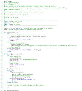
Build FM NRSC masks for SIGLENT SSA3000X/SVA1000Xs using a Python script
Many broadcast applications require monitoring a transmitter and observing the output amplitude vs. frequency. For FM radio applications, a common mask is defined by the National Radio Systems Committee (NRSC) and is commonly referred to as the FM NRSC mask.
A very helpful SIGLENT owner, Dan from Alabama Broadcast Services, LLC, built an FM NRSC Mask tool using our original AM NRSC mask python code
This program was built using Python 2.7 and helps create masks around user-defined center frequencies.
Here is a link to the zipped download of the finished Python code: SSA3XNRSC_FM_Limit.zip
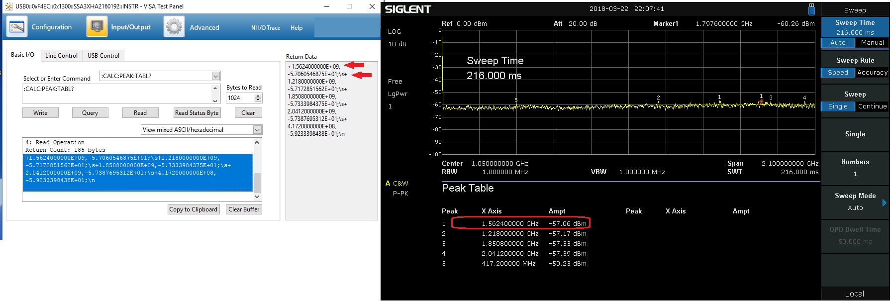
Programming Example: Return Peak Table Data with an SSA3000X Spectrum Analyser
The SIGLENT SSA3000X series of spectrum analysers have an on-screen peak detection that can be used to easily show the peak values in a
- Configure the instrument span, RBW, and amplitude to capture the signals of interest
- Send “:CALC:MARK:PEAK:TABL ON”
- Send “:CALC:PEAK:TABL? “ to return the peak table data
Here, we show the displayed peak table and the data return using a VISA interface:
Products Mentioned In This Article:
- SSA3000X Series please see HERE
Testing Intrinsic Safety Barrier fusing and circuitry using an Electronic Load
From Wikipedia: Intrinsic safety (IS) is a protection technique for safe operation of electrical equipment in hazardous areas by limiting the energy, electrical and thermal, available for ignition.
The idea is to minimise the risk of fire or explosion by physically eliminating any potential source of ignition.
Many IS circuits utilise special fusing and elements that are designed to dissipate the available power below certain temperature thresholds. During a fault condition, no component within the design can exceed this temperature rating.
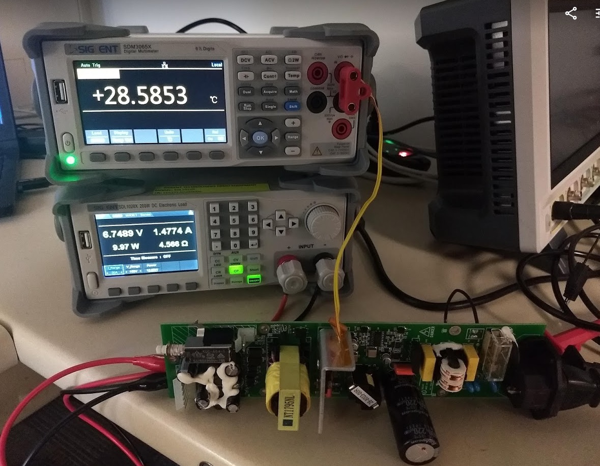
Testing the performance of this type of design is quite simple: Load the circuit to pull the maximum rated power and measure the temperature of all of the circuit elements (heat sinks, packaging, resistors, etc..).
In practice, you could use a power resistor network with proper heat sinking for the load but a more convenient solution is to use an electronic load like the SIGLENT SDL1000X series.
The SDL1000X is available in 200 and 300 W versions and features a Constant Power (CP) operation mode as well as Constant Resistance (CR), Constant Voltage (CV), as well as user-defined limits to ensure safe operation within the application test requirements.
- Connect the Device-Under-Test (DUT)
- Select Constant Power (CP) Mode
- Set the current (I_range) and voltage (V_range) ranges for the test
- Set the Power you wish the load to sink
- Activate the load input
After the specified time limit for your test (see your device/environment specifics for details), you can measure the components/design temperature using a thermal camera or direct temperature measurements using thermocouples and DMM like SIGLENTs SDM3000X series. In fact, the SDM3055-SC and SDM3065X-SC products feature the ability to monitor temperature on up-to-twelve thermocouples to provide multi-point temperature readings from different points on your design.
Be sure to check heatsinks and components that are expected to dissipate the most power, but also other peripheral components and traces that may carry unexpected loads during a fault.
NOTE: In this picture, we show an open power supply with no shielding or case. For more accurate measurement, we recommend leaving as much of the original design (shielding/case/metalwork) in place to get the most representative measurement possible.
Products Mentioned In This Article:
Programming Example: Controlling an SPD power supply via Sockets over LAN
Here is a Python 3.6 example of using sockets to control an SPD power supply connected to a computer using LAN.
NOTE: The SPD uses VXI-11 protocol for LAN. On some systems, it is helpful to use the VXI-11 format for the IP address:
“TCPIP::ip.add.re.ss::INSTR”
Here is the program in full:
Products Mentioned In This Article:
Siglent SPD Power Supplies please see HERE
Verification of a LAN connection using Telnet
Automating a test can dramatically increase the productivity, throughput, and accuracy of a process. Automating a setup involves connecting a computer to the test instrumentation using a standard communications bus like USB or LAN and then utilising code entered via a software layer (like LabVIEW, .NET, Python, etc..) to sequence the specific instrument commands and process data.
This process normally goes quite smoothly, but if there are problems, there are some basic troubleshooting steps that can help get your test up-and-running quickly.
In this note, we are going to show how to use Telnet to test the communications connection between an instrument and a remote computer using a LAN connection to ensure that it is working properly. Once the connection is verified, you can begin to work on the control software.
Telnet provides a means of communicating over a LAN connection. The Telnet client, run on a LAN connected computer, will create a login session on the instrument.
NOTE: The Telnet connection requires open sockets on the instrumentation. At this time, not all SIGLENT products feature open sockets. Check the product page FAQs or with your local SIGLENT support office for more information.
A connection, established between the computer and instrument, generates a user interface display screen with SCPI> prompts on the command line.
Using the Telnet protocol to send commands to the instrument is similar to communicating with USB. You establish a connection with the instrument and then send or receive information using SCPI commands. Communication is interactive: one command at a time.
The Windows operating systems use a command prompt style interface for the Telnet client.
STEPS
1. Power on and connect the instrument to the network via LAN
2. Verify that the Gateway, Subnet Mask, and IP address of the instrument are valid for the network you wish to use. This information is typically located in the System Information or IO menu. See the specific instrument user’s guide for more information on LAN settings.
3. On the computer, click Start > All Programs > Accessories > Command Prompt.
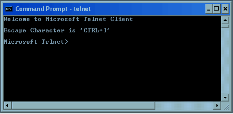
4. At the command prompt, type in telnet.
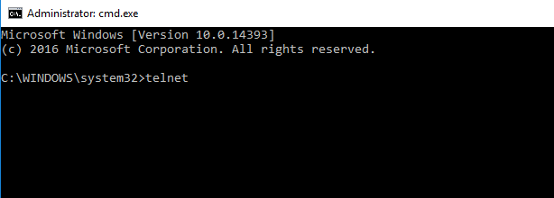
5. Press the Enter key. The Telnet display screen will be displayed.
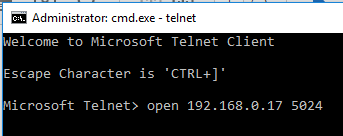
6. At the Telnet command line, type: open XXX.XXX.XXX.XXX 5024 where XXX.XXX.XXX.XXX is the instrument’s IP address and 5024 is the port. You should see a response similar to the following:
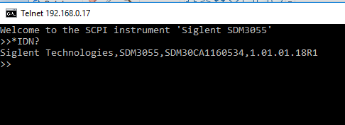
7. Now, you can enter any valid command for the specific instrument that you are controlling. See the specific programming guide for the instrument for more information.
This is especially helpful when you are planning a specific test sequence, the effect of delays/timing, or troubleshooting a command. You can send each command one-at-a-time and check the performance of the instrument.
*IDN? is a common identification string query (question or information request) that returns the information from the connected instrument
Open Socket LAN connection using Python
Automating a test can dramatically increase the productivity, throughput, and accuracy of a process. Automating a setup involves connecting a computer to the test instrumentation using a standard communications bus like USB or LAN and then utilising code entered via a software layer (like LabVIEW, .NET, Python, etc..) to sequence the specific instrument commands and process data.
In this note, we are going to show how to use Python to create a communications link between an instrument and a remote computer using a LAN connection. Once the connection is verified, you can begin to work on the control software.
NOTE: This example requires open sockets on the instrumentation. At this time, not all SIGLENT products feature open sockets. Check the product page FAQs or with your local SIGLENT support office for more information.
Python is an interpreted programming language that lets you work quickly and is very portable. Python has a low-level networking module that provides access to the socket interface. Python scripts can be written for sockets to do a variety of test and measurements tasks.
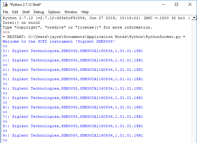
Here is a short script that opens a socket, sends a query, and closes the socket. It does this loop for 10 times.
1. Power on and connect the instrument to the network via LAN
2. Verify that the Gateway, Subnet Mask, and IP address of the instrument are valid for the network you wish to use. This information is typically located in the System Information or IO menu. See the specific instrument user’s guide for more information on LAN settings.
3. Download python and your favourite python editor (I use IDLE):
https://docs.python.org/2/library/idle.html
Start your python editor:

5. Open a new file by pressing File > New File.. and name the file
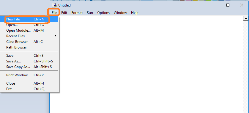
6. Copy and paste the code at the end of this note into the file editing window:
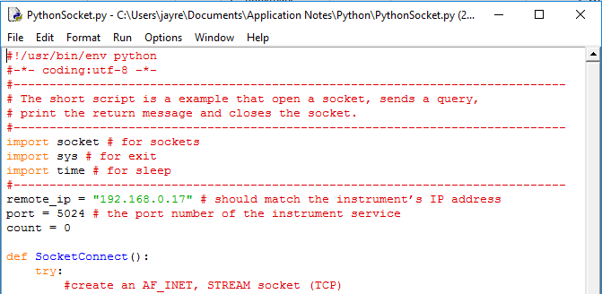
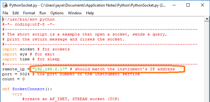
7. Change the IP address so that it matches the IP address of the instrument you wish to connect to:
Save the file:
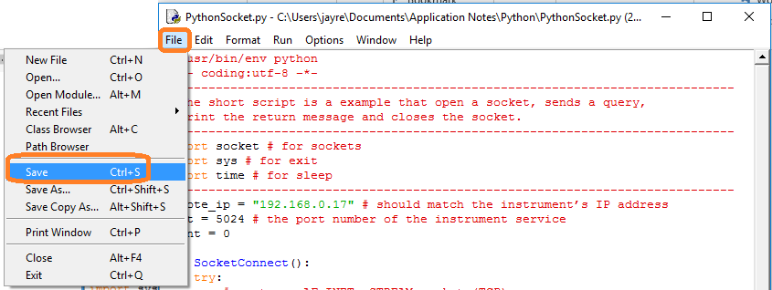
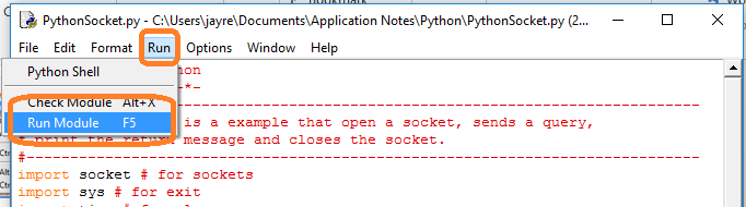
8. To Run, select Run and Run Module:
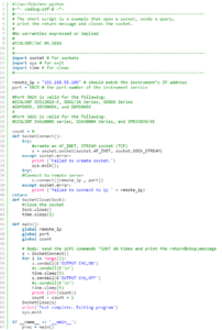
#!/usr/bin/env python
#-*- coding:utf-8 –*-
#—————————————————————————–
# The short script is a example that open a socket, sends a query,
# print the return message and closes the socket.
#—————————————————————————–
import socket # for sockets
import sys # for exit
import time # for sleep
#—————————————————————————–
remote_ip = “192.168.0.17” # should match the instrument’s IP address
port = 5024 # the port number of the instrument service
count = 0def SocketConnect():
try:
#create an AF_INET, STREAM socket (TCP)
s = socket.socket(socket.AF_INET, socket.SOCK_STREAM)
except socket.error:
print (‘Failed to create socket.’)
sys.exit();
try:
#Connect to remote server
s.connect((remote_ip , port))
info = s.recv(4096)
print (info)
except socket.error:
print (‘failed to connect to ip ‘ + remote_ip)
return sdef SocketQuery(Sock, cmd):
try :
#Send cmd string
Sock.sendall(cmd)
time.sleep(1)
except socket.error:
#Send failed
print (‘Send failed’)
sys.exit()
reply = Sock.recv(4096)
return replydef SocketClose(Sock):
#close the socket
Sock.close()
time.sleep(.300)def main():
global remote_ip
global port
global count# Body: send the SCPI commands *IDN? 10 times and print the return message
s = SocketConnect()
for i in range(10):
qStr = SocketQuery(s, b’*IDN?’)
print (str(count) + “:: ” + str(qStr))
count = count + 1
SocketClose(s)
input(‘Press “Enter” to exit’)if __name__ == ‘__main__’:
proc = main()Products Mentioned In This Article:
- SPD3000X please see HERE
Verification of a working remote communications connection using NI – MAX
Automating a test can dramatically increase the productivity, throughput, and accuracy of a process. Automating a setup involves connecting a computer to the test instrumentation using a standard communications bus like USB or LAN and then utilizing code entered via a software layer (like LabVIEW, .NET, Python, etc..) to sequence the specific instrument commands and process data.
This process normally goes quite smoothly, but if there are problems, there are some basic troubleshooting steps that can help get your test up-and-running quickly.
In this note, we are going to show how to use NI-MAX to test the communications connection between an instrument and a remote computer using both a USB and a LAN connection to ensure that they are working properly. Once the connection is verified, you can begin to work on the control software.
National Instruments Measurement and Automation Explorer (NI-MAX) is a free communications tool provided with NI’s VISA library.
You can learn more here: http://digital.ni.com/public.nsf/allkb/71544521BDE34FFB86256FCF005F4FB6
USB Connections
1. Power on and connect the instrument via USB cable to the computer. On a computer running Windows, the first time you connect the USB from an instrument should open a dialog box or show a notification of a new device being connected.
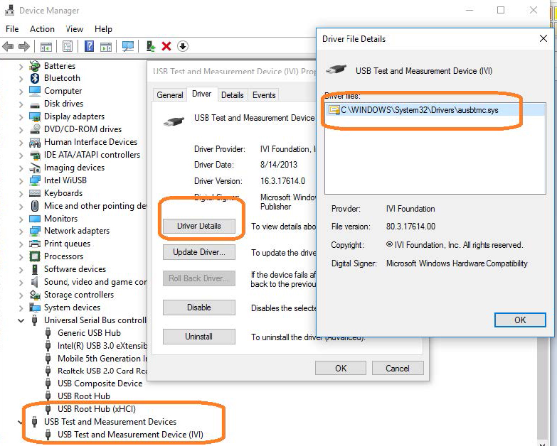
You can check the status of the USB connections by opening Device Manager located in the Control Panel menu of most Windows Operating systems and expanding the driver information as shown below in this Windows 10 example:
This indicates that the operating system recognizes the connected instrument as a test instrument.
If the device manager reports the USB connection as some other type of device (printer, camera, unknown, etc.), there is likely a problem linking the proper driver (ausbtmc.sys) to the instrument. One possible solution to this is to disable the driver, disconnect the USB cable, verify that ausbtmc.sys exists, and then reconnect the USB cable.
2. Run NI-MAX by left-clicking on the icon on the desktop or finding it via the start menu
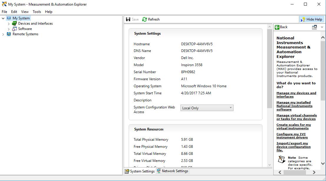
3. This will open the main window, as shown below:

4. Expand the “Devices and Interfaces” menu. You should see the instruments attached via USB with a brief description as shown for an SDS2000X oscilloscope below:
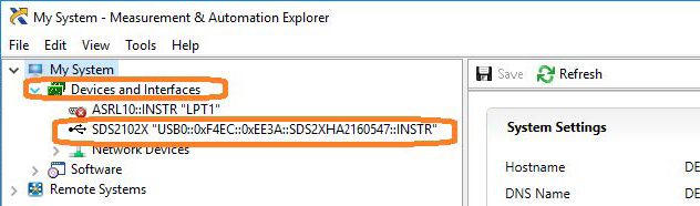
This indicates that a software application (NI-MAX) has correctly identified a test and measurement device (the oscilloscope) over the USB connection.
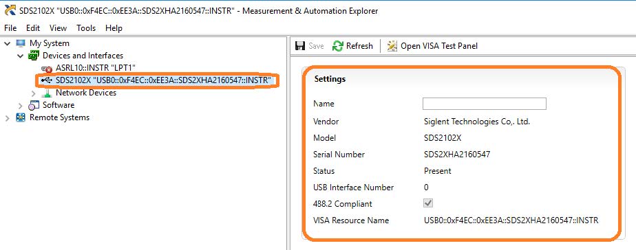
5. By left-clicking on the instrument, you can see additional information about it:
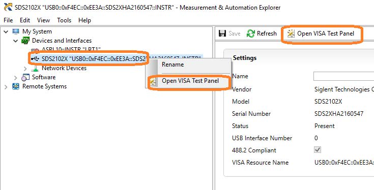
6. To further test the connection, right-click on the instrument and select Open VISA Test Panel or select it from the side bar:
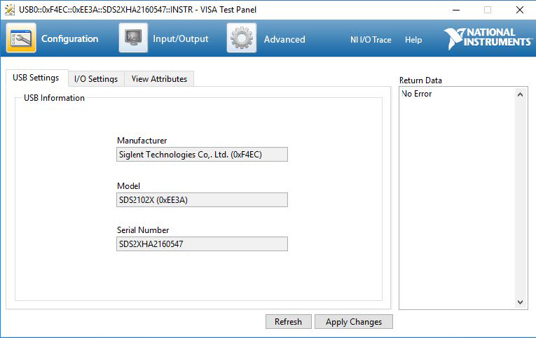
The VISA Test Panel window shows some helpful information, including the instrument manufacturer, model, serial number, and the USB identifier (VISA Address) along the top.
7. Another useful item in the VISA Test Panel is the Input/Output function. This mode allows you to send specific instrument commands and receive instrument responses.
This is especially helpful when you are planning a specific test sequence, the effect of delays/timing, or troubleshooting a command. You can send each
command one-at-a-time and check the performance of the instrument.Select Input/Output > Basic I/O > and Enter the command in the text window:
– *IDN? is a common identification string query (question or information request) that returns the information from the connected instrument
– /n is a termination character that represents a new line. This is the standard termination character for SIGLENT instrumentation.
– Write will send the command to the instrument
– Read will pull data from the instrument
– Query will perform a read and then a write command to request and return data from the instrument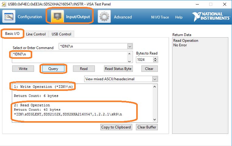
USB Checklist
– Is the USB port configured properly on the instrument? Some instruments feature USB ports that can be configured as TMC (Test and Measurement) or Printer communication ports. The USB port should be set to USBTMC or similar for remote control.
– Try a direct connection to the controlling computer. USB hubs or long connections may cause issues.
– Try a different USB cable. Connectors can go bad or prove to be faulty.
– Try a different USB port on the computer.
– On machines running Windows, check the Device Manager. Test instrumentation should appear as USB Test and Measurement Device (IVI) and use the AUSBTMC.SYS driverLan Connections
1. Power on and connect the instrument via LAN cable to a LAN network connected to the computer you wish to use.
You can check the status of the LAN connection by using a software tool like NMAP: https://nmap.org/
NMAP allows you to scan networks and identify IP addresses.
First, identify the LAN connection for the instrument. This is typically located in the System menu under IO or LAN settings.
Here is the IO information for an SDS2000X oscilloscope:
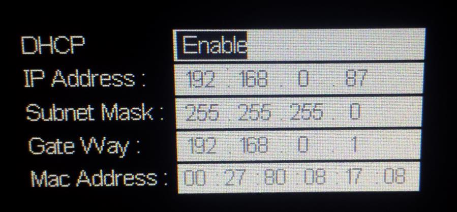
DHCP Enabled will automatically configure the instrument connection settings and apply a valid IP address. With DHCP enabled, the IP address may change over time. It is recommended to check the instrument IP address and then confirm that it is visible on the network using NMAP:
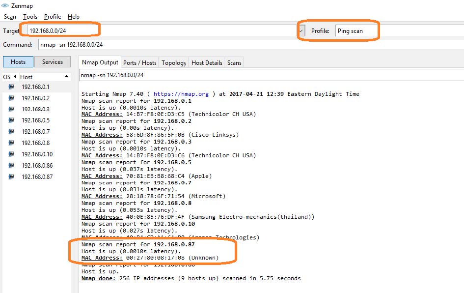
Here, we are performing a Ping (short scan to identify what IP addresses are being used) over the range of IP addresses that may match the instrument.
This can be performed by setting the target using the “/24” extension. This scans 24 bits For example, 192.168.10.0/24 would scan the 256 hosts between
192.168.10.0 and 192.168.10.255Here is more information from NMAP:
https://nmap.org/book/man-target-specification.htmlFor example, to ping all IP addresses that start with 192.168.0., set the target as follows:
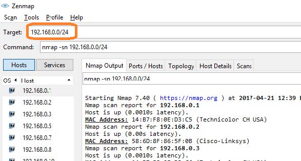
Note the IP address and MAC address that identify your instrument.
2. Run NI-MAX by left-clicking on the icon on the desktop or finding it via the start menu
This will open the main window, as shown below:

3. Unlike USB, there is not an easy way to identify all of the instruments connected via LAN.
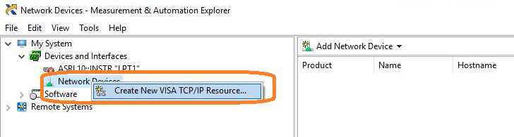
In many cases, you will have to manually add the LAN instrumentation. Recall from Step 2, our instrument IP address is 192.168.0.87
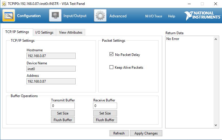
Right-click on Network Devices, and select Create New VISA TCP/IP Resource:
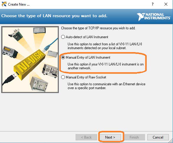
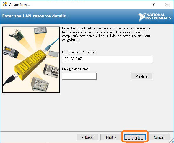
4. Select Manual Entry of LAN:
5. Enter the IP address and press Validate
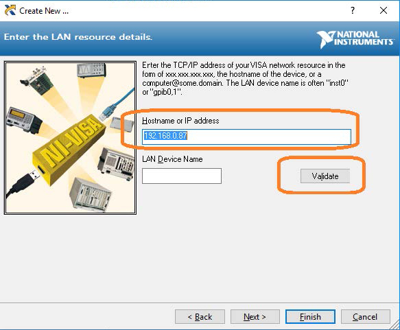
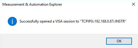
6. After successfully creating a TCP/IP connection, select finish
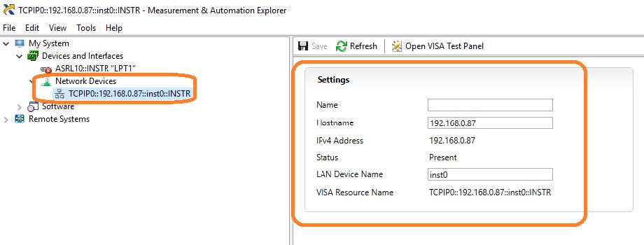
7. After the system updates it’s configuration, the instrument will appear in the Network Devices menu:
8. To further test the connection, right-click on the instrument and select Open VISA Test Panel or select it from the side bar:
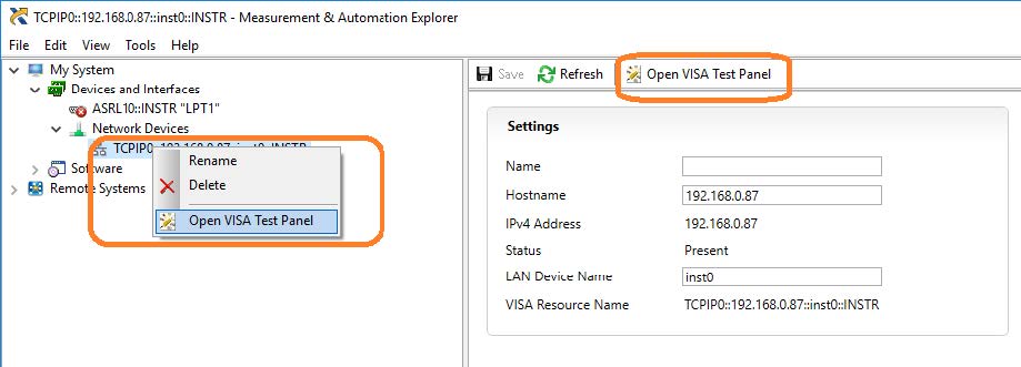
The VISA Test Panel window shows some helpful information, including the TCP/IP identifier (VISA Address) along the top.
9. Another useful item in the VISA Test Panel is the Input/Output function. This mode allows you to send specific instrument commands and receive instrument responses.
This is especially helpful when you are planning a specific test sequence, the effect of delays/timing, or troubleshooting a command. You can send each command one-at-a-time and check the performance of the instrument.
Select Input/Output > Basic I/O > and Enter the command in the text window:
– *IDN? is a common identification string query (question or information request) that returns the information from the connected instrument
– /n is a termination character that represents a new line. This is the standard termination character for SIGLENT instrumentation.
– Write will send the command to the instrument
– Read will pull data from the instrument
– Query will perform a read and then a write command to request and return data from the instrument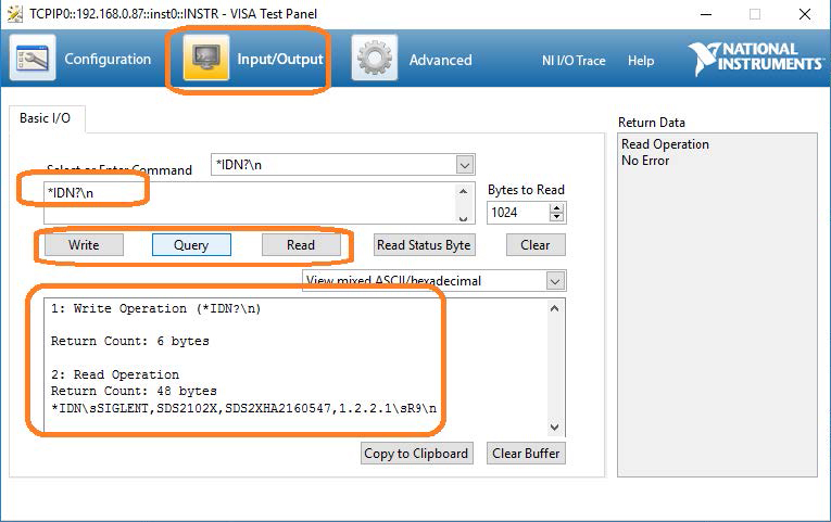
Programming Example: Create a stair-step waveform using Python and PyVISA using LAN (SDG1000X, SDG2000X, SDG6000X)
The SIGLENT SDG series of arbitrary waveform generators can use waveforms created programmatically.
The waveform data can be sent as individual samples formatted as binary little-endian, 2s complement values.
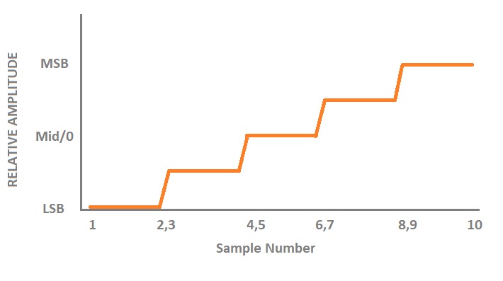
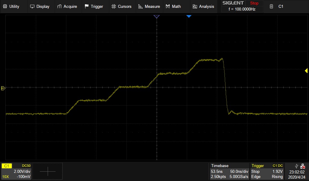
In this programming example, we create a 10 point arbitrary waveform that starts at the least-significant bit and steps up to the most-significant bit to help with understanding the required sample format as well as provide a base for your own waveform creation.
Here is a picture of the desired waveform:
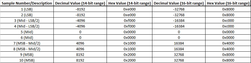
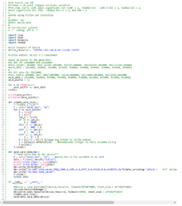
 The SDG waveform data requires each sample to first be formatted as binary, little-endian, 2’s complement. For easier human viewing, the example enters the data in hex format and then “unhexes” the data before it is added to the command string which is then sent to the instrument.
Here is a table showing the value of each sample and the value in hex for 14-bit (SDG1000X series) and 16-bit (SDG2000X/SDG6000X) instruments:
Here is an oscilloscope capture of a single burst of this waveform:
Products Mentioned In This Article: