Your cart is currently empty!
Author: James
Operation Tutorial to Perform Simulated CC Operation in PCR-LE Series
1. Overview
In PCR-LE Series, simulated CC operation can be achieved by setting the current limit in AC mode. This method is based on its internal system as the ammeter monitors the output current and the arithmetic circuit controls the output voltage. The functions and characteristics of this method are described as below;
1) Response becomes slow with this method.
Figure 1 shows its response when the load is rapidly changed.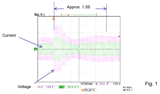
2) The output current is stable if the output voltage is around the rated voltage, while the output current is fluctuated if the output voltage is low.
E.g.) The output current is stable if the load is operated by 100V voltage. On the other hand, the output voltage is fluctuated if the load is operated by 10V voltage.
3) Applied power can be limited if the load voltage fluctuation is large.
E.g.) If the load voltage starts from 100V but decreases to 50V with time due to the load resistance fluctuation, the internal loss of PCR-LE becomes larger so that its protection circuit may shut off the output.
This method has some disadvantages as stated above, however it may be useful operation for an application that the load changes slowly such as a heater.2. Operating Procedures
Please follow the steps below to perform this method:
1) Return to the factory default setting to be safe;
– Press PRESET (SHIFT+6) key. Then, ‘RESET’ is displayed and SHIFT+ENT are flashing. – Press ENT key while holding down SHIFT key.
2) Set the output voltage and frequency to be applied.
Note) If you do not want to rapidly apply the voltage due to using the load with resistance characteristics, the following step is recommended to minimize the voltage overshoot; – Set the output voltage to low.
– After step 7, gradually increase the voltage to switch from CV to CC operation.
3) Set ‘TRIP DISABLE (Circuit breaker trip is disabled.)’ (Refer to page 34 of user’s manual: ‘Action to perform when the current limit is exceeded’);
– Press I key.
– Press TRIP key (software key). – Choose DISABLE.
4) Press ESC key to go back to the home screen.
5) Set the current limit value. This value is equivalent to the simulated CC value.
6) Press ESC key to go back to the home screen.
7) Connect your load. Turn OUTPUT on to apply simulated CC.Products Mentioned In This Article:
- PCR-LE Series please see HERE
PLZ Series Easy Way to Expand Electronic Load Capacity in CV Mode
PLZ Series Easy Way to Expand Electronic Load Capacity in CV Mode
Our electronic load PLZ Series has a well-known feature that a master/slave parallel operation expands an output capacity in the same model, controlled slave units by a master unit (except for PLZ-4WL).
In this article, we are going to further explain how to increase the capacity by parallel connection with different models such as PLZ-5W Series (CV mode) and PLZ-4W Series.
How to Build Parallel System:
1. How to Operate PLZ-4W Series
Connect PLZ-4W to PLZ-5W in parallel and set PLZ-4W to CR or CC mode.
2. How to Connect
See Figure 1 for the example: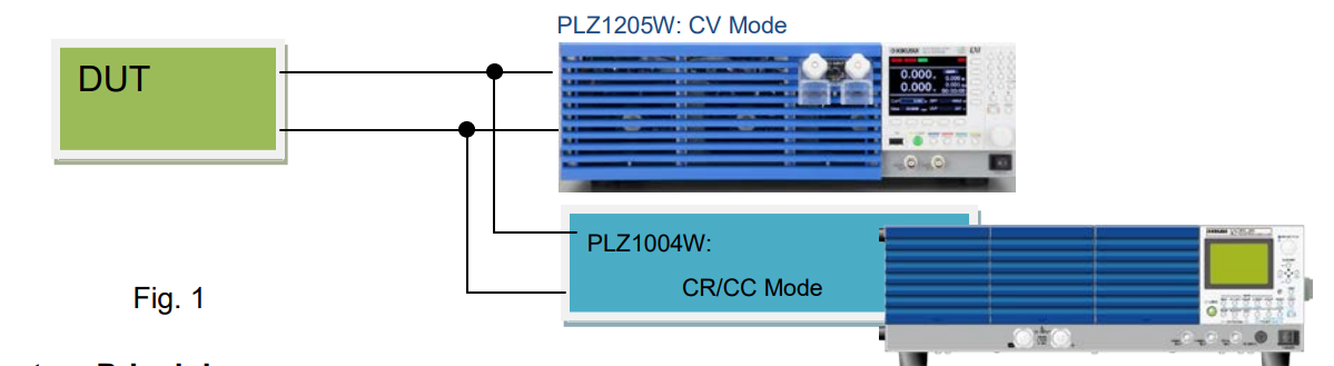
3. System Principle
Figure 2 shows the equivalent circuit of the above system. The red dotted line describes that the DUT and PLZ1205W are connected in parallel; PLZ1205W is in CV mode so that
PLZ1004W and the DUT should be in CC or CR operation to keep a stable operation. Note: In the example below, operating PLZ1004W in CP mode may cause an unstable operation.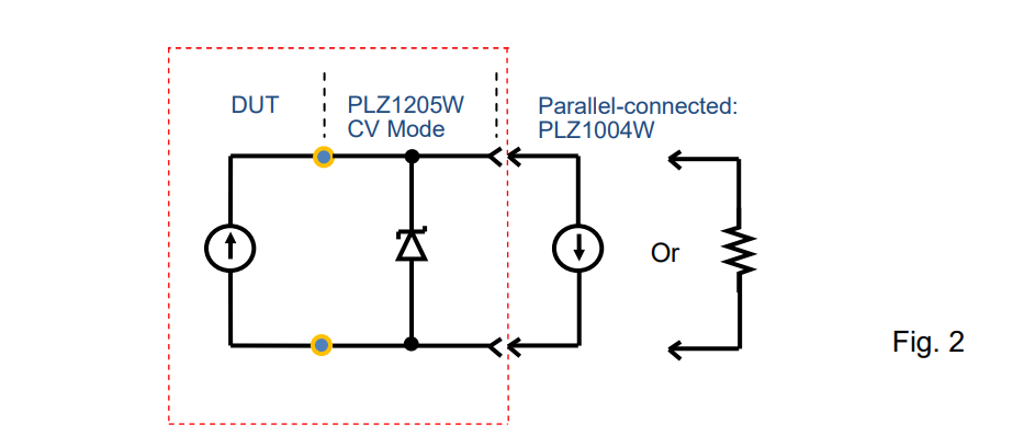
4. Note
In the example above, it is necessary that PLZ1205W will not become a full load while controlling PLZ1004W; it depends on the DUT’s characteristics how to sink the current by PLZ1004W.Products Mentioned In This Article:
Kikusui Electronic Loads please see HERE
Using Electronic Load to Battery Charger Testing
Using Electronic Load to Battery Charger Testing
A battery charger is a device that can recharge a secondary cell or rechargeable battery. Every battery charger being used requires the testing and such testing system must include something to simulate a battery.
An electronic load can provide the best solution for the battery charger testing to simulate the actual behaviour of a battery. It is very useful to test the charger operation over the entire battery voltage range.
Test Method
Figure 1 shows the schematic diagram of the testing setup to sink the current from the battery charger to the electronic load;
● Connect an electronic load and a DC power supply in parallel.
● Operate the electronic load in constant voltage (CV) mode to keep the CV at the electronic load terminals.
● Operate the DC power supply in constant current (CC) mode to flow the CC*1 into the
electronic load.
*1: The CC is set to 100 mA.
Figure 2 shows the equivalent circuit of this testing system.
Some battery chargers determine the state of the battery first, but there is no problem in this testing system that the charger can detect the voltage at the electronic load terminals.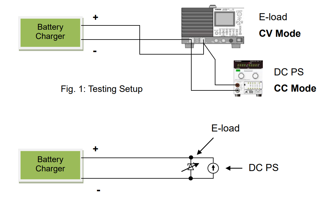
Products Mentioned In This Article:
For the full Kikusui Electronic Load range please see HERE
Blown Fuse Testing Precautions When Using Electronic Load
Blown Fuse Testing Precautions When Using Electronic Load
This article will address some precautions on the blown fuse testing such as the unit testing or cable and fuse testing (see Figure 1) and fuse component testing.
1. Test System
A DC power supply, cable, fuse and electronic load are connected as shown in Figure 1.
1) Prepare a DC power supply whose current and voltage capacity are greater than a test range.
2) Set an electronic load to CC mode and set a test current from an electronic load panel.
3) DC power supply: Turn the output on. Electronic load: Turn the load on.
4) Monitor a current with an electronic load ammeter. In general, an electronic load ammeter is more accurate than that of power supply.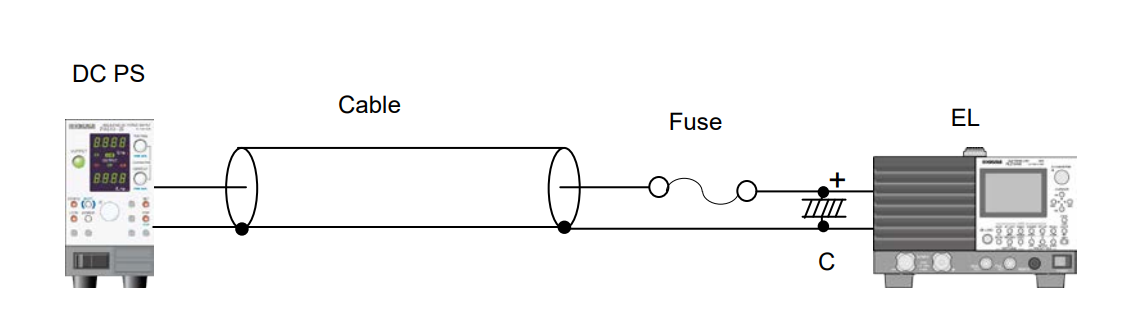
Fig. 1
2. Precautions
1) Cable inductance may cause oscillations on electronic loads, especially using longer cables. To prevent it, lower the response speed (RESPONSE) of electronic load (Example for PLZ-4W Series: set RESPONSE to 1/10).
2) If the oscillations persist longer even after lowering the response speed, place an electrolytic capacitor (C = approx. 1000μF) on input terminals of electronic load as shown in Figure 1.
3) Electronic loads can also dynamically change a current (E.g. 0.5A-5A, Duty: 30%, at 200HZ). The rise and fall times vary with the response setting and slew rate setting.Products Mentioned In This Article:
Kikusui’s full range of DC Power Supplies and Electronic Loads please see HERE
How to Measure Output Impedance of Power Supply with Bipolar Power Supply PBZ Series
How to Measure Output Impedance of Power Supply with Bipolar Power Supply PBZ Series
PBZ Series is a bipolar power supply that can be also operated in quadrant 2 to sink the current. This function enables you to measures an output impedance of DUT (e.g. fuel cell, DC power supply) by using PBZ Series as an electronic load. PBZ Series equips with an AC waveform generation function so that you do not need to prepare another oscillator.
The following procedures explain how to flow the load current of DC5A and AC1Arms (1 kHz) to DUT power supply. To accurately measure the impedance, an AC voltmeter and AC ammeter are required.
<Procedures>
1) Reset PBZ to the factory default, if needed. SHIFT+POWER ON
2) Set PBZ to the constant current (CC) mode. Press the CONFIG key (menu page 1/7). MODE
POLARITY: BIPOLAR/UNIPOLAR *Press▼ to move the cursor. Turn the knob to specify the setting. CONTROL: CC
3) Set a DC current on PBZ.
Press the DC key.
DC -5.000A (Note: Negative current should be set.)
4) Set an AC current on PBZ. Press the AC key. FUNC Sine wave
AMPL 2.8 A p-p (AC will flow at 1Arms.) FREQ 1000.00Hz (1 kHz)
AC ON
5) Turn DUT’s output on.
After checking that the negative voltage is applied on the PBZ COM terminal and the positive voltage is applied on the PBZ OUT terminal, turn DUT’s output on.
6) Turn PBZ’s OUTPUT on.
PBZ will sink the current from DUT.
7) Check the current.
Press the MEASURE key.
FUNC DC : Measure DC current/voltage *Turn the knob. FUNC AC : Measure AC current/voltage
8) Turn PBZ and DUT off.
Turn PBZ’s OUTPUT off. Then, Turn DUT’s output off.
Please be noted that the negative voltage might be applied to the DUT by wrong procedures. If the DUT has a diode in parallel with the output, it will be protected that the sink current flows through the diode.Products Mentioned In This Article:
- PBZ Series please see HERE
Vibration Testing Method for Automotive Wiring Harness Connector
1. Test Condition: Conduct the vibration testing on the automotive wiring harness connector under supplied at 12 VDC/1 A.
2. Test Criteria: If the resistance of the wiring harness connector exceeds 7.0 Ω for more than 1 microsecond (us),
it defines an electrical discontinuity.
3. Test Circuit: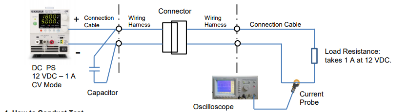
4. How to Conduct Test
• Calculate the resistance of the wiring harness connector based on the current change using Ohm’s law (measure the current and the time interval with an oscilloscope); E.g. If the current changes from 1.0 A to 0.63 A; it would be approx. 7.0 Ω (excluding the resistance of the connection cables).
• If the connection cables are too long from the DC power supply to the wiring harnesses, place a capacitor at their connecting point to reduce the cable’s inductance.
• Operate the DC power supply in constant voltage (CV) mode. Since the voltage is constant, the current depends on the connector’s contact resistance and the load resistance. So, the connector’s contact resistance can be accurately measured.
• The resistance calculation accuracy is affected by the inductance of the wiring harnesses and the connection cables. To minimize the induction effect, make them into a twisted pair and as short as possible.
• Use a non-inductive resistance for the load resistance (Do not use an electronic load instead, otherwise the current cannot be accurately measured.)
• We recommend you to use a current probe for the current waveform observation. If connecting a resistor to observe the waveform, you may not obtain an accurate measurement especially if the voltage becomes lower due to noise generated from the connector.Products Mentioned In This Article:
- PMX Series please see HERE
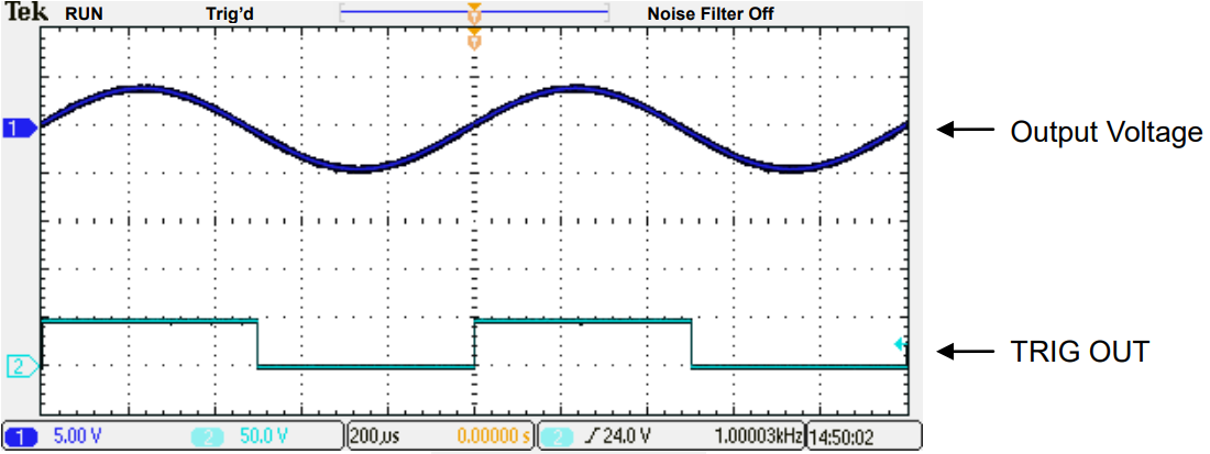
PBZ Series: How to Output Synchronised Square Wave from TRIG OUT Terminal
PBZ Series: How to Output Synchronised Square Wave from TRIG OUT Terminal
To transmit a synchronised trigger pulse for output, you can create a trigger signal output (TRIG OUT): through the sequence function or with the following settings. When you output a square wave signal, it is easier to configure the following settings. The settings are available in a single operation only, not in a synchronized operation.
1. Output ExamplePBZ outputs at 1 kHz.
2. Settings
Note: Set TRIG OUT to SYNC in the menu page 5/5. See the actual setting examples below: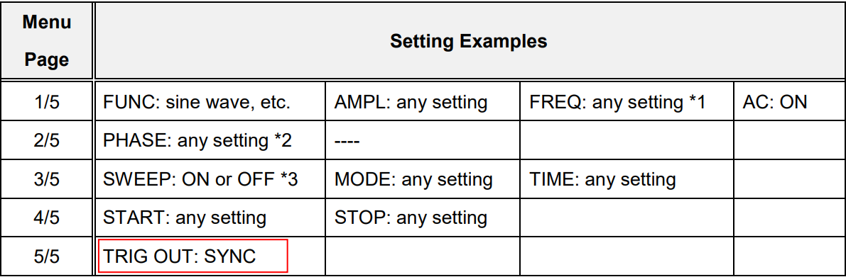
*1: If SWEEP is set to OFF, set AC signal frequency in the FREQ setting.
*2: You can change the phase of output and trigger signal output (TRIG OUT) in the PHASE setting. *3: If TRIG OUT is set to SYNC, the square wave signal is outputted regardless of the SWEEP
setting.Products Mentioned In This Article:
- PBZ Series please see HERE
Current and Voltage Accuracy in Two Setting Methods
Current and Voltage Accuracy in Two Setting Methods
When setting the output current or voltage from DC power supply, a higher accuracy can be achieved by panel setting or remote PC setting instead of ammeter adjustment. Below explains the accuracy difference between these two methods taking PMX35-1A and PMX18-5A as an example.
CC Accuracy
1. Panel Setting/Remote PC Setting Accuracy
When setting CC with the SET button and knob, CC setting accuracy regards as how an actual CC value differs from a true value.
E.g.) For PMX35-1A and PMX18-5A, the setting accuracy value is: ± (0.3% of setting + 0.1% of rating).
When setting 300mA from the panel, the following error is included: PMX35-1A: ± (0.3 x 0.003 + 1 x 0.001) = ± 0.0019 (A)
PMX18-5A: ± (0.3 x 0.003 + 5 x 0.001) = ± 0.0059 (A)
It means that PMX18-5A may cause a larger error with this setting method. If you need to pass 1A, a higher accuracy can be achieved through PMX35-1A.
The same applies to the remote PC setting.
2. Ammeter Adjustment Accuracy
When setting CC (300mA) by adjusting an ammeter, the ammeter accuracy regards as how an actual CC value differs from a true value.
E.g.) For PMX35-1A and PMX18-5A, the ammeter accuracy value is: ± (1% of reading + 5 digits);
When setting 300mA by adjusting the ammeter, the following error is included: PMX35-1A: ± (0.3 x 0.01+ 0.005) = ± 0.008 (A)
PMX18-5A: ± (0.3 x 0.01+ 0.005) = ± 0.008 (A)
It means that PMX35-1A andPMX18-5A obtain the same error results with ammeter adjustment.Generally, the higher accuracy can be obtained by setting from panel or PC instead of adjusting
the ammeter.
Therefore, the current accuracy will be determined which method to be used.
Conclusion:
To improve the current accuracy;
1) Choose DC power supply whose rated current is close to your required value.
2) Set current from SET button or PC instead of ammeter adjustment.CV Accuracy
1. Panel Setting/Remote PC Setting Accuracy
When setting CV with the SET button and knob, CV setting accuracy regards as how an actual CV value differs from a true value.
E.g.) For PMX35-1A and PMX18-5A, the setting accuracy value is: ± (0.2% of setting + 0.1% of rating).
When setting 5V from the panel, the following error is included: PMX35-1A: ± (5 x 0.002 + 35 x 0.001) = ± 0.045 (V)
PMX18-5A: ± (5 x 0.002 + 18 x 0.001) = ± 0.028 (V)
It means that PMX35-1A may cause a larger error with this setting method.
If you need to apply 5V, a higher accuracy can be achieved through PMX18-5A. The same applies to the remote PC setting.
2. Voltmeter Adjustment Accuracy
When setting CV (5V) by adjusting a voltmeter, the voltmeter accuracy regards as how an actual CV value differs from a true value.
E.g.) For PMX35-1A and PMX18-5A, the voltmeter accuracy value is: ± (0.5% of reading + 2 digits);
When setting 5V by adjusting the voltmeter, the following error is included: PMX35-1A: ± (5 x 0.005 + 0.04) = ± 0.065 (V)
PMX18-5A: ± (5 x 0.005 + 0.04) = ± 0.065 (V)
It means that PMX35-1A andPMX18-5A obtain the same error results with voltmeter adjustment.Generally, the higher accuracy can be obtained by setting from panel or PC instead of adjusting
the voltmeter.
Therefore, the voltage accuracy will be determined which method to be used.
Conclusion:
To improve the voltage accuracy;
1) Choose DC power supply whose rated voltage is close to your required value.
2) Set voltage from SET button or PC instead of voltmeter adjustment.
Please be sure to verify each setting accuracy and meter accuracy before setting the output.Products Mentioned In This Article:
PMX Series please see HERE
How to Enable Positive/Negative Output from DC Power Supply
How to Enable Positive/Negative Output from DC Power Supply
DC power supply can provide dual (positive and negative) output by following the method described in Section 1 below.
1. How to Produce Positive/Negative Output
1. Connect Power Supply 1 to Power Supply 2 in series.
2. Connect COM terminal to GND terminal.
3. Set each voltage from Power Supply 1 and 2.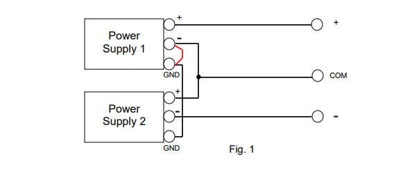
2. Dual Tracking Function
Generally, DC power supply can feature ‘master-slave series operation’ function. With this function, Power Supply 1 acts as the controller for Power Supply 2.
E.g.) If Power Supply 1 outputs 5V voltage, Power Supply 2 automatically outputs also 5V voltage.
In dual (positive/negative) output power supply, this function is called as ‘dual tracking’ function that varies positive and negative voltages simultaneously.
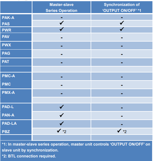
Some Kikusui’s DC power supplies support the master-slave series operation. For the function availability, please check the user’s manual of your model or see Table 1 in the next page.
In addition, if you output from two units of PCR-LE Series with 2P05-PCR-LE (optional board for single-phase three-wire output) in DC output mode, these units can act as dual tracking power supply.3. Dual Tracking Function Availability
Products Mentioned In This Article:
To view all Kikusui Power Supplies please see HERE
PLZ Series: How to Effectively Improve Safety during Load Testing of Non-isolated AC/DC Converter
PLZ Series: How to Effectively Improve Safety during Load Testing of Non-isolated AC/DC Converter
Considering minimising the potential shock hazard, the use of an isolation transformer or regulated power supply is critical during load testing of a non-isolated AC/DC converter (such as PFC). This white paper explains; what happens without an isolation transformer or regulated AC power supply and how important these are for safety reasons.
1. What happens if non-isolated AC/DC converter is directly connected to electronic load?
Figure 1: Since the DUT is non-isolated, the capacitor of electronic load, which placed at its DC input, passes the current though the enclosure of electronic load to the leakage breaker, thus shutting the breaker off.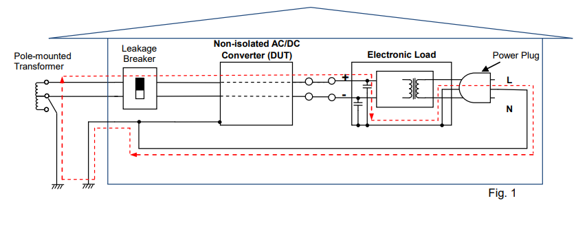
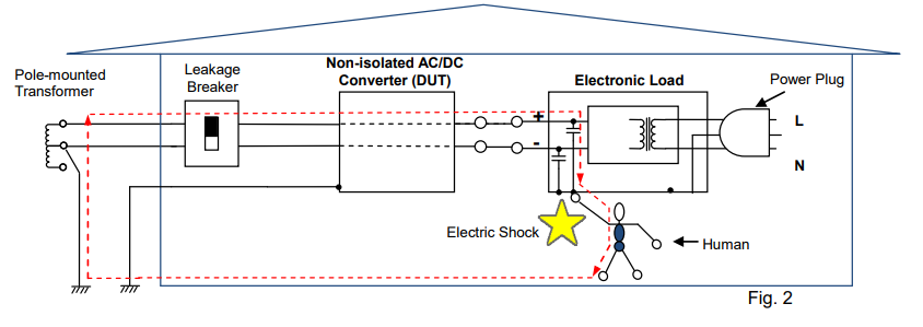
Figure 2: Example that the GND terminal of electronic load (at the power plug) is not grounded; The leakage breaker will not shut itself off, but the voltage is applied to the enclosure of electronic load. Contacting such electronic load could expose an operator to an electric shock. Note: Our user’s manual advises users; ‘Be sure to earth ground the product to prevent electric shock’.
2. Preventive Action
To prevent the above interruption or shock hazard, add the isolation transformer or AC regulated power supply as shown in Figure 3, which can provide the electrical isolation between the utility power line and the primary and secondary terminals of DUT. This can greatly reduce the potential shock hazard for an operator.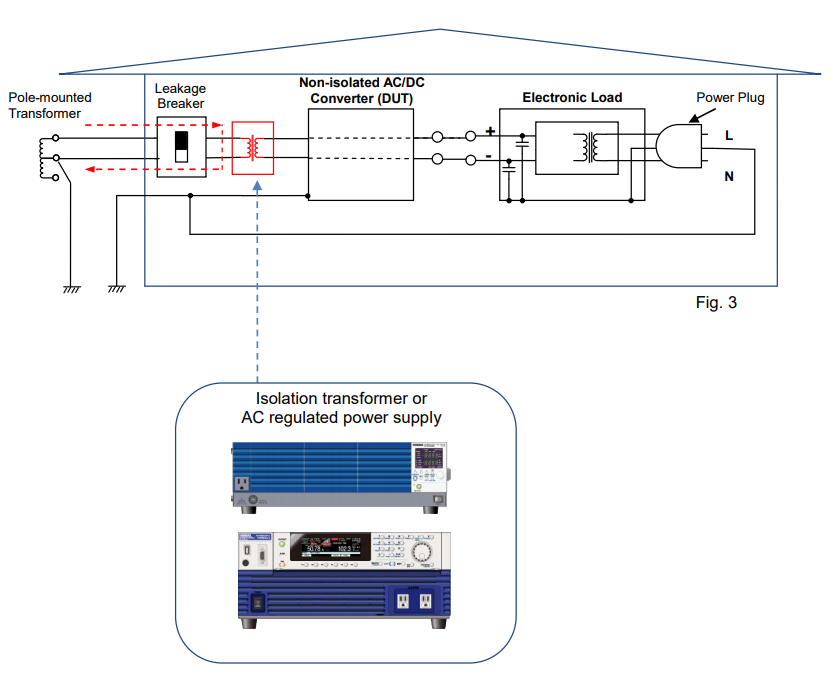
3. Non-isolated DC/AC Converter Testing
The same situation may occur while performing a load testing on a non-isolated DC/AC converter (such as power conditioner) by using our AC electronic load PCZ1000A. In this case also, we highly recommend to use an isolation transformer or regulated power supply.Products Mentioned In This Article:
To view all PLZ Series please see HERE
PBZ Series: How to Change Pulse Width Using Sequence Function
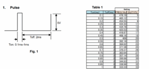
PBZ Series: How to Change Pulse Width Using Sequence Function
PBZ Series can change the square waveform frequency and duty cycle. Using the sequence function, you can also change the pulse width. The following sections explain how to change the pulse width according to Ton/Toff specified in figure 1 and table 1.
2. Create and Execute Sequence
1) Square wave frequency and duty cycle: See the ‘Setting’ column in Table 1. FREQ=1/ (Ton+Toff), DUTY=Ton/ (Ton+Toff)
2) Enter the above data into the sequence creation software (Wavy for PBZ).
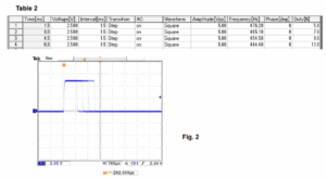
Table 2 shows the sequence example of the first four steps.
Note: Enter 0 in the Phase field. Interval should be shorter than one time period of the square waveform.Figure 2 shows the actual generated waveform (for Ton).
Products Mentioned In This Article:
PBZ Series please see HERE
How to Calculate Input Current for PCR-LE/MA Series
How to Calculate Input Current for PCR-LE/MA Series
Before installing PCR-LE or MA Series, you may want to know how much current should be supplied from the distribution board. The best way is to calculate the current consumption (= input current) of your PCR-LE or MA Series. Here are the examples how to calculate the input current based on your output requirement (your output voltage and current):
Example 1: PCR3000LE
Condition: Input Voltage: Single-phase, 200 VAC
Output Voltage: 230 VAC rms, 10 A
Method 1: Calculate based on Input Current Characteristics Graph
See Figure 1 from User’s Manual of PCR-LE Series – ‘Operating Characteristics’ (Page 93).
1. Calculate output current ratio
The output voltage is 200 V or higher: e.g. 230 V as above example. Calculate the percentage of output power to the rated power. This percentage is regarded as output current ratio:
Output power: 230 V x 10 A = 2,300 VA
Output current ratio: 2,300 VA / 3,000 VA = 0.766 = 76.6% 2. Find input current
You can find the input current through the red points on the above graph: e.g. If output current ratio is 76.6%, the input current is approx. 21 A.Method 2: Calculate based on Efficiency Characteristics Graph
See Figure 2 from User’s Manual of PCR-LE Series – ‘Operating Characteristics’ (Page 93).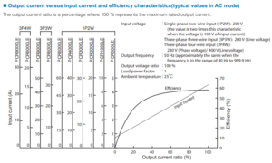
1. Calculate output current ratio
The output voltage is 200 V or higher: e.g. 230 V as above example. Calculate the percentage of output power to the rated power. This percentage is regarded as output current ratio:
Output power: 230 V x 10 A = 2,300 VA
Output current ratio: 2,300 VA / 3,000 VA = 0.766 = 76.6%
2. Find efficiency
You can find the efficiency through the red points on the above graph: e.g. If output current ratio is 76.6%, the efficiency is approx. 57%.
3. Calculate input power (active power: W)Input power (active power): 2,300 VA / 0.57 = 4,035 W
4. Calculate apparent power (VA) and input currentThe power factor from the specification: 0.97
Input power (apparent power): 4,035 W / 0.97 = 4,159 VA Input current: 4,159 VA / 200 V = 20.79 A = approx. 21 A.Example 2: PCR1000MA
Condition: Input Voltage: Single-phase, 200 VAC
Output Voltage: 200 VAC rms, 3 A
Method 1: Calculate based on Input Current Characteristics Graph
See Figure 3 from User’s Manual of PCR-MA Series – ‘Operating Characteristics’ (Page 63).
1. Calculate output current ratio
The output voltage is 200 V or higher: e.g. 200 V as above example. Calculate the percentage of output power to the rated power. This percentage is regarded as output current ratio:
Output power: 200 V x 3 A = 600 VA
Output current ratio: 600 VA / 1,000 VA = 0.6 = 60%2. Find input current
You can find the input current through the red points on the above graph: e.g. If output current ratio is 60%, the input current is approx. 4.4 A.Method 2: Calculate based on Efficiency Characteristics Graph
See Figure 4 from User’s Manual of PCR-MA Series – ‘Operating Characteristics’ (Page 63).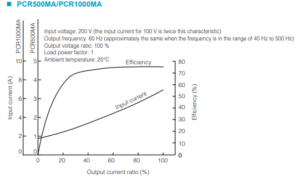
1. Calculate output current ratio
The output voltage is 200 V or higher: e.g. 200 V as above example. Calculate the percentage of output power to the rated power. This percentage is regarded as output current ratio:
Output power: 200 V x 3 A = 600 VA
Output current ratio: 600 VA / 1,000 VA = 0.6 = 60%
2. Find efficiency
You can find the efficiency through the red points on the above graph: e.g. If output current ratio is 60%, the efficiency is approx. 75%.
3. Calculate input power (active power: W)Input power (active power): 600 VA / 0.75 = 800 W
4. Calculate apparent power (VA) and input currentThe power factor from the specification: 0.9
Input power (apparent power): 800 W / 0.9 = 888 VA Input current: 888 VA / 200 V = 4.44 A = approx. 4.4 A.
Below is the Operating Characteristics Graph for PCR2000MA/4000MA as reference.
You can also calculate the input current for PCR2000MA/4000MA using the same method as above.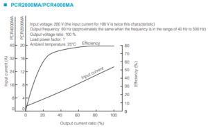
Products Mentioned In This Article: